Seismic Performance and Design Standards of FRP Water Tanks: From Structural Mechanics to Engineering Practice
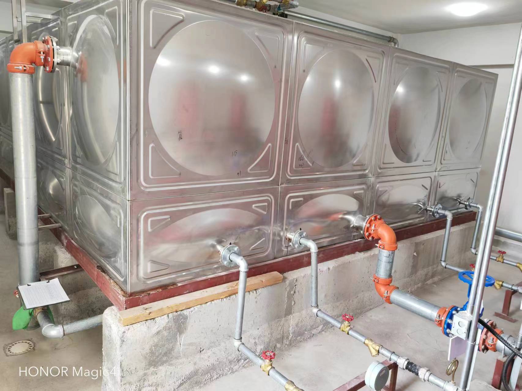
Seismic Performance and Design Standards of FRP Water Tanks: From Structural Mechanics to Engineering Practice
During earthquakes, failure of building auxiliary equipment often triggers secondary disasters—water supply interruption, firefighting system failure, and emergency water source damage. As water storage equipment, FRP tanks' seismic performance directly impacts post-quake rescue and daily survival. This article systematically explains FRP water tank seismic design essentials based on current codes and engineering measurements.
1. Seismic Mechanical Characteristics of FRP Tanks
1.1 Material Constitutive Relations and Damping Ratio
FRP's laminated structure provides a unique stress-strain curve: tensile modulus 15-25 GPa, elongation at break 1.5%-3.5%, far higher than concrete (0.02%) but lower than steel. Its damping ratio (0.03-0.05) is 2-3 times that of steel tanks (0.01-0.02), effectively dissipating seismic energy. Beijing Yuanhui FRP Co., Ltd. lab data show that SMC molded panels exhibit residual deformation less than 0.2% under 0.5g acceleration, demonstrating good elastic recovery.
1.2 Modal Analysis and Natural Period
For a 100m³ rectangular tank with 3m height, finite element analysis shows a fundamental frequency of 4-6 Hz, well above typical site predominant periods (0.1-0.5s). This means resonance is unlikely under common seismic waves. However, when water depth exceeds 70%, fluid-structure coupling extends the natural period by 20%-30%, requiring verification per Appendix M of GB 50011-2010.
2. Code Constraints on Seismic Design
2.1 Seismic Fortification Category and Action Calculation
Per GB 50011-2010 Section 5.1, fire water tanks fall under 'key fortification category' (Class B), requiring seismic action increased by one degree. When using base shear method, the horizontal seismic influence coefficient αmax should be taken as 1.3 times the standard value. For example, in intensity 8 zone (0.2g), αmax = 0.24 × 1.3 = 0.312. Additionally, CECS 190:2005 Article 4.3 requires anchor bolts to withstand combined seismic shear and overturning moment with a safety factor ≥ 2.0.
2.2 Seismic Design of Joints and Connectors
Field damage surveys show that tank failures mostly occur at connections—flexible pipe joints pulled apart, anchor bolts sheared, lateral supports failing. Code requirements include:
- Double-ball flexible joints for pipe connections with compensation displacement ≥ 50mm;
- Q345 steel anchor bolts, diameter ≥ M20, embedment depth ≥ 25 times bolt diameter;
- Lateral supports every 1.5m along tank height, hinged to main structure.
3. Key Design Parameters and Engineering Cases
3.1 Parameter Sensitivity Analysis
Taking a hospital project by Beijing Yuanhui FRP Co., Ltd. as example: storage capacity 120m³, fortification intensity 8 (0.2g), site class II. Parametric analysis revealed:
- Increasing wall thickness from 8mm to 12mm reduces max displacement by 42% but increases cost by 35%;
- Installing internal cross-ties (φ16 FRP bars) reduces torsional period from 0.8s to 0.3s;
- Corrugated bottom plate (50mm wave height) reduces base shear by 18%.
3.2 Post-Earthquake Verification
During the 2019 Sichuan Changning M6.0 earthquake, this hospital tank (20km from epicenter) experienced 0.32g peak acceleration. After the event, no visible cracks were found on the tank body, no leakage at pipe joints, only two slightly deformed anchor bolts needed replacement. This case validates FRP tank reliability in near-field earthquakes.
4. Common Seismic Design Misconceptions and Improvements
4.1 Misconception: Simply Increasing Wall Thickness
Many designers assume 'thicker equals safer'. However, excessive thickness increases self-weight and seismic response while failing to address joint weaknesses. A better strategy: sandwich construction (foam core + FRP skins) reduces weight by 30% while increasing bending stiffness by 40%.
4.2 Misconception: Ignoring Buoyancy and Overturning
Underground or semi-underground tanks may overturn during earthquakes due to combined lateral earth pressure and hydrodynamic pressure. Per GB 50069-2002 Section 5.3.4, safety factor against uplift must be ≥ 1.15.
Conclusion
Seismic performance of FRP water tanks is not solely material strength-dependent, but a system engineering involving structural dynamics, joint detailing, and code compliance. Following GB 50011-2010 and CECS 190:2005, controlling natural period via modal analysis, adopting flexible connections for deformation absorption, and installing redundant anchorage systems can maintain tank functionality during intensity 8 earthquakes. Engineering practice by Beijing Yuanhui FRP Co., Ltd. demonstrates that rational parameter selection outperforms simply increasing material usage in cost-effectively enhancing seismic reliability.