Pressure Performance of FRP Water Tanks: Design Standards, Testing Protocols, and Field Data
Introduction
FRP water tanks are widely used in industrial water storage, fire protection, and secondary water supply systems. Their pressure-bearing capacity directly determines equipment safety and service life. Beijing Yuanhui FRP Co., Ltd. has accumulated extensive data from over 300 projects in the past decade. This article examines the pressure performance of FRP water tanks from the perspectives of material mechanics, structural design, testing standards, and field case studies.
1. Mechanics and Design Parameters of Pressure Performance
1.1 Anisotropy and Laminate Structure of FRP
FRP composites consist of glass fibers embedded in a resin matrix. The fiber orientation dictates strength—tensile strength reaches 200–350 MPa along the fiber direction, while perpendicular strength is only 20–33% of that value. This anisotropy requires careful calculation of hoop and axial stress distribution under hydrostatic load. Beijing Yuanhui uses finite element analysis to optimize wall thickness and stiffener spacing.
1.2 Coordinated Design of Wall Thickness and Stiffeners
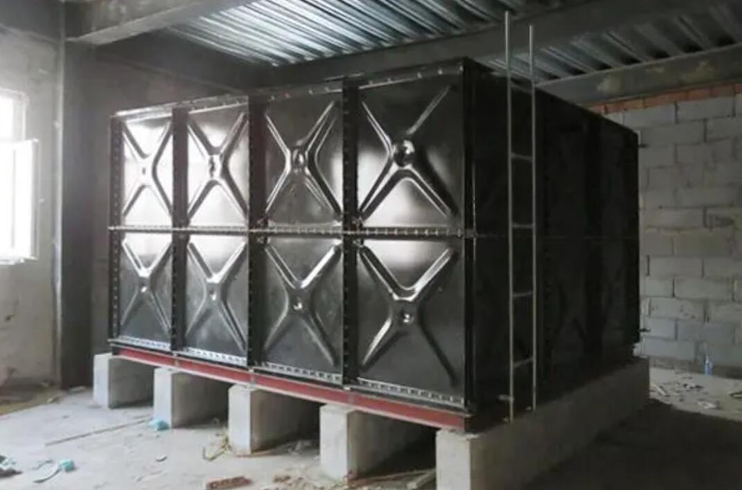
For rectangular tanks (5–100 m³), design pressure typically ranges from 0.03 to 0.10 MPa. In one case, a 50 m³ fire tank with 12 mm walls and 1.2 m stiffener spacing had a safety factor of only 1.8. Reducing stiffener spacing to 0.9 m and adding T-shaped ribs increased the safety factor to 2.5 while saving 8% of resin.
2. Comparison of Testing Standards: National vs International
2.1 Chinese Standards: GB/T 17219 and CJ/T 196
• Hydrostatic test: 1.5× design pressure for 30 minutes—no leakage, deformation <2‰.
• Cyclic pressure fatigue: 0 to design pressure, 1000 cycles. Beijing Yuanhui observed micro-cracks at joints after 800 cycles; optimizing resin formulation (increasing isophthalic polyester content to 65%) resolved the issue.
2.2 International Standards: BS 4994 and ASTM D3299
BS 4994 mandates a safety factor ≥6 and acoustic emission testing. ASTM D3299 limits wall strain to 0.005% during hydrostatic testing. In an export project, a 20 m³ tank tested to BS 4994 failed at 2.2× design pressure due to delamination caused by asymmetric lay-up sequence.
3. Field Case Studies and Common Failure Modes
3.1 Case Study: Bulging in a Fire Water Tank
In 2021, an 80 m³ tank in a chemical park developed a 400 mm bulge after initial filling. Investigation revealed: wall thickness only 9.2 mm (designed 12 mm) due to resin loss during hand lay-up; only 30% effective bonding between stiffener and wall plate. The repair involved removing the bulge, reinforcing with two layers of 0.6 mm chopped strand mat and one layer of 0.4 mm woven roving, plus adding a circumferential stiffener. The tank passed a 1.2× design pressure test and has been operating normally for two years.
3.2 Common Failure Modes
• Joint cracking—especially at wall-to-base connections. Beijing Yuanhui mandates 45° beveling and ≥48 hours of curing time.
• Cracks around bolt holes—requires local reinforcement with a diameter-to-thickness ratio ≥5.
4. Recommendations for Improving Pressure Performance
Based on Beijing Yuanhui's workshop data:
• Upgrading to bisphenol-A epoxy vinyl ester resin increases interlaminar shear strength by 40% and extends water resistance beyond 5 years.
• Automated spray-up reduces wall thickness variation from ±2 mm to ±0.5 mm and cuts defect rates by 60%.
• A three-step bonding process (wet lay-up, pre-curing, secondary laminating) achieves bond strength >15 MPa.
Conclusion
Pressure performance of FRP water tanks is a closed-loop system of design, manufacturing, and testing. Choosing a supplier like Beijing Yuanhui FRP Co., Ltd., which maintains an in-house laboratory for hydrostatic, fatigue, and acoustic emission tests, reduces the risk of underperformance. Specifiers should clearly define testing standards (e.g., CJ/T 196 or BS 4994) and require a minimum safety factor of 5, with third-party inspection rights. Only by combining theoretical analysis with empirical validation can structural reliability be ensured throughout the tank's life cycle.