Thermal Insulation Performance of FRP Water Tanks: Engineering Insights from Material Structure to Application Scenarios
Introduction: Why FRP Tank Insulation Demands More Than Just Foam
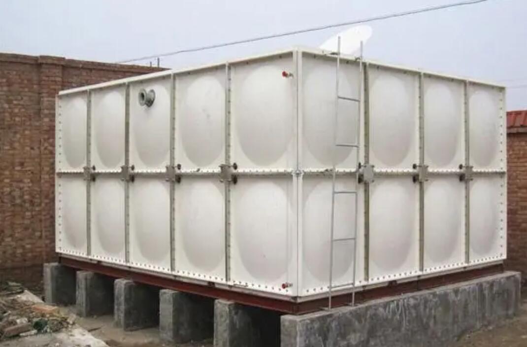
FRP (Fiberglass Reinforced Plastic) water tanks are widely used in potable water, fire protection, and industrial cooling due to their corrosion resistance and light weight. However, when water must be kept above 40°C (e.g., domestic hot water) or ambient temperature drops below -10°C (e.g., outdoor installations in northern regions), insulation performance directly impacts operating costs and system reliability. Beijing Yuanhui FRP Co., Ltd. has observed in over a decade of field projects that many users oversimplify insulation as merely 'thickening polyurethane,' neglecting thermal bridges at joints, bottom support conduction, and pipe penetration sealing. This article analyzes insulation design from heat transfer fundamentals and engineering cases.
1. Three Core Components of FRP Tank Insulation Systems
1.1 Interface between Inner Liner and Insulation Layer
The inner liner of FRP tanks (SMC molded or hand-layup) must have proper surface roughness to ensure adhesion of polyurethane foam. Beijing Yuanhui applies a 'surface roughening + primer' process, achieving peel strength above 0.3 MPa to prevent delamination under thermal cycling. The typical insulation is rigid polyurethane foam with density 40-50 kg/m³ and thermal conductivity ≤0.024 W/(m·K). Any void larger than 2 mm diameter can increase local thermal conductivity by 15-20%.
1.2 Outer Protective Layer: UV and Impact Resistance
The protective jacket (FRP or steel sheet) must resist UV degradation. In high-solar-radiation regions like Northwest China, UV absorbers should be added. Beijing Yuanhui's five-year project in Xinjiang used 2 mm FRP cladding, with insulation performance degradation less than 8%. For impact-prone locations (e.g., fire pump rooms), 1.2 mm galvanized steel is recommended, offering approximately 3× higher impact strength than FRP.
1.3 Bottom and Top Insulation Reinforcement
The tank bottom contacting the base creates a major thermal bridge. Field measurements show bottom heat flux is 2-3 times higher than sidewalls. Standard practice: 50 mm XPS board beneath the tank, plus a 20 mm air gap. Top insulation thickness should be 10-15% thicker than sidewalls because hot air rising increases top heat loss by about 25%.
2. Key Performance Parameters: K-Value and Annual Heat Loss
FRP tank insulation is quantified by the heat transfer coefficient K (W/(m²·K)). Per GB/T 3280-2016, with 50 mm foam, K should be ≤0.8. Beijing Yuanhui's lab data: 80 mm polyurethane (density 45 kg/m³) achieves K=0.52, equivalent to a daily temperature drop of ≤0.8°C (ambient -10°C, water 60°C, tank volume 20 m³). These results come from the company's 'Insulation Efficiency Test Platform' with 32 thermocouples and heat flux meters.
In practice, heat loss also depends on wind speed, aspect ratio (longer ratio = slower cooling), and pipe diameters. Example: Beijing Yuanhui's hot water tank for a ski resort in Inner Mongolia (4m×3m×2.5m, 80 mm foam, average winter wind 3.5 m/s) showed actual daily heat loss of 0.9°C, below the design value of 1.2°C.
3. Typical Application Scenarios and Selection Guide
3.1 Outdoor Installation in Severe Cold Regions
When ambient temperature drops below -20°C, anti-freeze circulation or electric heat tracing is necessary. Beijing Yuanhui's project in Harbin used a '80 mm polyurethane + 30 mm rock wool' double layer, plus self-regulating heat tape (15 W/m) on pipes. A 100 mm concrete insulation pad under the tank reduced foundation heat loss by 70%. No freezing failure occurred over three winters.
3.2 Industrial Hot Water Storage (60-90°C)
Above 70°C, polyurethane foam degrades faster. For temperatures up to 90°C, phenolic foam (service temperature 150°C, B1 fire rating per GB 8624) is preferred. Beijing Yuanhui's project in a Jiangsu chemical plant (80°C water, 80 mm phenolic foam + stainless steel liner) showed only 5% compressive strength loss after three years, versus 15% for polyurethane.
3.3 Fire Protection Tanks
Fire tanks require water temperature ≥4°C, but over-insulation can exceed roof load limits. The solution is to optimize thermal bridges rather than simply increasing foam thickness. Beijing Yuanhui's high-rise project in Shenzhen used '50 mm polyurethane + low-conductivity nylon supports,' achieving K=0.7 while reducing total tank weight by 12% compared to conventional design.
Conclusion: Insulation Is a System Engineering, Not Material Stacking
FRP tank insulation performance depends on the synergy of liner interface, foam continuity, outer jacket durability, and thermal bridge management. Beijing Yuanhui FRP Co., Ltd. advises specifiers to demand complete heat transfer coefficient calculations and measured test data, not just foam thickness. For severe cold or high-temperature industrial applications, steady-state thermal simulation (e.g., FLUENT) is recommended to validate design. Insulation life-cycle management is equally critical—inspect outer jacket sealing every 3-5 years to prevent moisture ingress that degrades insulation.