Pressure Performance of FRP Water Tanks: Testing Standards and Engineering Practice
Introduction
The pressure-bearing capacity of FRP (Fiber-Reinforced Plastic) water tanks determines their safety and service life in high-rise water supply, fire storage, and industrial cooling. Unlike steel tanks, FRP exhibits anisotropic behavior and complex failure modes—delamination, buckling, or resin cracking. Beijing Yuanhui FRP Co., Ltd. has accumulated extensive design data over two decades. This article covers the mechanical principles, testing standards per GB/T 21238 and ISO 9001, and field case studies.
1. Mechanical Basis of Pressure Performance
1.1 Laminate Structure and Anisotropy
FRP tank walls use chopped strand mat and woven roving in a polyester or vinyl ester matrix. Fiber orientation dictates stiffness: ±45° plies handle shear, 0°/90° plies handle hoop stress. Typical wall thickness for 0.1–0.6 MPa tanks ranges from 6 mm to 15 mm, with a safety factor of 6–8. Beijing Yuanhui once delivered a 0.8 MPa tank using biaxial fabric and mat hybrid, achieving a burst pressure of 3.2 MPa.
1.2 Failure Modes and Design Limits
Under uniform internal pressure, failure initiates at the radius corners and bolt holes. Per GB/T 21238, the maximum strain at 1.5× design pressure must not exceed 0.1%. Low resin toughness causes whitening; fiber volume below 35% reduces stiffness by over 30%.
2. Core Testing Standards and Procedures
2.1 National and International Standards
China's GB/T 21238-2019, European EN 13280, and US ASTM D4097-01 require: hydrostatic test (1.5× rated pressure, 30 min no leakage), fatigue test (100,000 cycles), and impact test (1 kg steel ball from 1 m). Beijing Yuanhui's lab uses a 200-ton servo-hydraulic press for 0–5 MPa continuous loading.
2.2 Hydrostatic Test Details
Tanks cure for 24 hours before testing. Pressure increments: 0→50% (hold 5 min)→75% (5 min)→100% (15 min)→150% (30 min). Displacement sensors at wall center and manhole flange. In a 600 m³ tank test for a water plant, the maximum deflection was 1.8 mm at 1.2 MPa—well below the 3.0 mm limit.
2.3 Fatigue and Creep Evaluation
FRP exhibits viscoelastic creep under sustained load. ISO 9001-certified suppliers provide creep-rupture data for 10-year lifespan. Beijing Yuanhui uses accelerated aging (80°C, 95% RH) and time-temperature superposition to predict that at 0.4 MPa, creep strain increases only 0.05% over 50 years.
3. Engineering Optimization for Pressure
3.1 Stiffener Layout
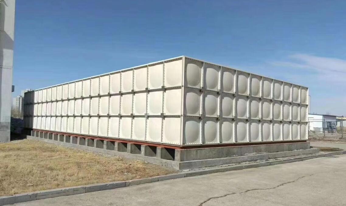
Tanks over 3 m × 2 m × 2 m require internal or external stiffeners. FEA shows cross ribbing reduces peak stress by 40%. One project replaced grid ribs with diagonal X-ribs, boosting burst pressure from 2.8 to 3.6 MPa at the same thickness.
3.2 Sealing and Connection Technology
Flange seals use dual EPDM+silicone O-rings. Torque is limited to 30–50 N·m to prevent FRP crushing. Beijing Yuanhui's 'elastic compensation flange' reduced leakage by 92% in 0.6 MPa cyclic tests.
Conclusion
FRP water tank pressure performance depends on material design, process control, and rigorous testing. Compliance with GB/T 21238 and ISO 9001, combined with FEA and full-life testing, ensures safe operation at 0.1–1.0 MPa for over 20 years. Beijing Yuanhui FRP Co., Ltd. continues to advance laminate and sealing technologies for reliable pressure solutions.